
Inductor is a commonly used component in switching power supply, because its current, voltage phase is different, so theoretically the loss is zero. Inductors are often used as energy storage components, and are often used together with capacitors on input filter and output filter circuits to smooth the current.
Inductor is a commonly used component in switching power supply, because its current, voltage phase is different, so theoretically the loss is zero. Inductors are often used as energy storage components, and are often used together with capacitors on input filter and output filter circuits to smooth the current. An inductor, also known as a choke, is characterized by the "great inertia" of the current flowing through it. In other words, because of the flux continuity, the current through the inductor must be continuous, otherwise large voltage spikes will be generated.
Inductance is a magnetic element, so it has the problem of magnetic saturation. Some applications allow inductance to saturate, some allow inductance to saturate from a certain current value, and some applications do not allow inductance to saturate, which requires a distinction in specific lines. In most cases, the inductance operates in the "linear zone", where the value of the inductance is a constant and does not vary with the terminal voltage and current.
However, there is a non-negligible problem in switching power supply, that is, the winding of inductor will lead to two distributed parameters (or parasitic parameters), one is inevitable winding resistance, and the other is distributed stray capacitance related to winding process and material. The stray capacitance has little effect at low frequencies, but it becomes apparent as the frequency increases. When the frequency rises above a certain value, the inductor may become capacitive. If the stray capacitors are "concentrated" into a single capacitor, the capacitance characteristics at a certain frequency can be seen from the inductor equivalent circuit.
When analyzing the working condition of the inductor in the line or drawing the voltage and current waveform diagram, the following characteristics may be considered:
1. When current I flows through inductor L, the energy stored by inductor L is: E=0.5×L×I2 (1)
2. In a switching cycle, the relationship between the change of the inductor current (peak to peak value of ripple current) and the voltage at both ends of the inductor is: V=(L×di)/dt (2); it can be seen that the magnitude of ripple current is related to the inductor value.
3. Just as capacitors have charge and discharge currents, inductors also have charge and discharge voltage processes. The voltage across the capacitor is proportional to the integral of the current (an · second), and the current across the inductor is proportional to the integral of the voltage (volt · second). As long as the inductor voltage changes, the current change rate di/dt will also change. The forward voltage increases the current linearly, and the reverse voltage decreases the current linearly.
The size of ripple current will also affect the size of the inductor and output capacitance. ripple current is generally set to the maximum output current of 10%~30%, so for the buck type power supply, the peak current through the inductor is 5%~15% larger than the output current of the power supply.
Calculating the correct inductance value is very important for selecting the appropriate inductance and output capacitance to obtain the minimum output voltage ripple.
Inductor is a commonly used component in switching power supply, because its current, voltage phase is different, so theoretically the loss is zero. Inductors are often used as energy storage components, and are often used together with capacitors on input filter and output filter circuits to smooth the current. An inductor, also known as a choke, is characterized by a "great deal of inertia" in the current flowing through it. In other words, because of the flux continuity, the current through the inductor must be continuous, otherwise large voltage spikes will occur.
Inductance is a magnetic element, so it has the problem of magnetic saturation. Some applications allow inductance to saturate, some allow inductance to saturate from a certain current value, and some applications do not allow inductance to saturate, which requires a distinction in specific lines. In most cases, the inductance operates in the "linear zone", where the value of the inductance is a constant and does not vary with the terminal voltage and current.
However, there is a non-negligible problem in switching power supply, that is, the winding of inductor will lead to two distributed parameters (or parasitic parameters), one is inevitable winding resistance, and the other is distributed stray capacitance related to winding process and material. The stray capacitance has little effect at low frequencies, but it becomes apparent as the frequency increases. When the frequency rises above a certain value, the inductor may become capacitive. If the stray capacitors are "concentrated" into a single capacitor, the capacitance characteristics at a certain frequency can be seen from the inductor equivalent circuit.
 |
|||||||||||||||||||||||||||||||||||||||||||||||||||||||||||||||||||||||||||||||||
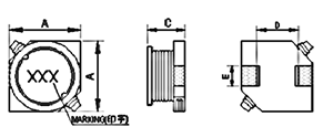
| 1. Shape And Size of five Rings (unit:mm) | |||||||||||||||||||||||||||||||||||||||||||||||||||||||||||||||||||||||||||||||||
   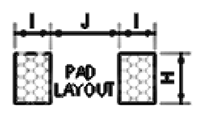   |
|||||||||||||||||||||||||||||||||||||||||||||||||||||||||||||||||||||||||||||||||
|
|||||||||||||||||||||||||||||||||||||||||||||||||||||||||||||||||||||||||||||||||
| 2. The five rings are numbered | |||||||||||||||||||||||||||||||||||||||||||||||||||||||||||||||||||||||||||||||||
|
CDRS 0628 – 221 K 1 2 3 4 |
|||||||||||||||||||||||||||||||||||||||||||||||||||||||||||||||||||||||||||||||||
| (1). Type :CDRS patch power inductor model (CDRS) | |||||||||||||||||||||||||||||||||||||||||||||||||||||||||||||||||||||||||||||||||
| (2). Size :External dimension, outer diameter 6.0mm, height 2.8mm(According to size) ( 0628 ) | |||||||||||||||||||||||||||||||||||||||||||||||||||||||||||||||||||||||||||||||||
| (3). Inductance : "221" shows 220uH(Example: "221"for 220uH) ( 221 ) | |||||||||||||||||||||||||||||||||||||||||||||||||||||||||||||||||||||||||||||||||
| (4). Inductance Tolerance :"M:±20%, "K":±10% , "J":±5% ( K ) | |||||||||||||||||||||||||||||||||||||||||||||||||||||||||||||||||||||||||||||||||


