
Common mode inductors (Choke), also known as Common mode Choke, are used to filter Common mode EMI signals in switching power supplies of computers. In the design of the board, the common mode inductor also plays the role of EMI filtering, which is used to suppress the outward radiation emission of the electromagnetic wave generated by the high-speed signal line.
The common mode inductor is essentially a bidirectional filter: on the one hand, it is necessary to filter out the common mode electromagnetic interference on the signal line, on the other hand, it is necessary to suppress the electromagnetic interference from itself, so as to avoid affecting the normal work of other electronic equipment in the same electromagnetic environment.
Why are common mode inductors EMI resistant? To figure this out, we need to start with the structure of the common mode inductor.
The filter circuit of the common mode inductor, La and Lb are the common mode inductor coils. The two coils are wound on the same core with the same number of turns and phase (winding in reverse). In this way, when the normal current in the circuit flows through the common mode inductor, the current will generate a reverse magnetic field in the inductor coil wound in the same phase and cancel each other. At this time, the normal signal current is mainly affected by the resistance of the coil (and a small amount of damping caused by leakage inductance). When the common mode current flows through the coil, due to the homogeneity of the common mode current, the magnetic field in the same direction will be generated in the coil and increase the inductive reactance of the coil, so that the coil shows high impedance and produces a strong damping effect, so as to attenuate the common mode current and achieve the purpose of filtering.
In fact, if one end of the filter circuit is connected to the interference source and the other end is connected to the interfered device, La and C1, Lb and C2 constitute two groups of low-pass filters, which can control the common mode EMI signal on the line at a very low level. The circuit can not only inhibit the external EMI signal incoming, but also attenuate the EMI signal generated when the line itself is working, which can effectively reduce the EMI interference intensity.
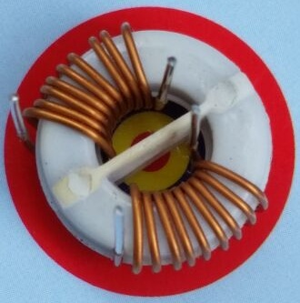
A kind of small common mode inductor manufactured in china, adopts high frequency noise suppression strategy, common mode choke coil structure, signal attenuation, small size, easy to use, has the advantages of good balance, easy to use, high quality and so on. Widely used in double balance tuners, multi-frequency transformers, impedance transformers, balanced and unbalanced conversion transformers. And so on.
There is a kind of common mode filter inductor/EMI filter inductor using ferrite core, and bifilar winding countermeasures of noise suppression, high common mode noise suppression and low differential mode noise suppression, suppress interference sources and low differential mode noise signal is difficult to deformation in the high speed signal, small volume, it has good balance, the advantages of convenient use and high quality. It is widely used in suppressing EMI noise of electronic equipment, USB line of personal computer and peripheral equipment, IEEE1394 line of DVC, STB, LCD display panel, low voltage differential signal and so on.
| Common-mode Inductor | 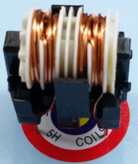 |
 |
||||
| HLFV129 TYPE | ||||||
|
PART NO |
Inductance |
DC |
Rated |
Rated |
Temperature |
TEST |
|
The five rings of the goods |
min(m H) |
Resistance |
Current |
Voltage |
Rise Max |
Voltage |
|
inductance value |
Max (Ω) |
(Amp) |
AC/DC |
℃ |
VAC(V) |
|
|
HLFV129-601U-1A |
0.6 |
0.060 |
1.0 |
250V |
40.0 |
2000 |
|
HLFV129-601U-2A |
0.6 |
0.050 |
2.0 |
250V |
40.0 |
2000 |
|
HLFV129-601U-3A |
0.6 |
0.030 |
3.0 |
250V |
40.0 |
2000 |
|
HLFV129-102U-1A |
1.0 |
0.070 |
1.0 |
250V |
40.0 |
2000 |
|
HLFV129-102U-2A |
1.0 |
0.050 |
2.0 |
250V |
40.0 |
2000 |
|
HLFV129-102U-3A |
1.0 |
0.035 |
3.0 |
250V |
40.0 |
2000 |
|
HLFV129-202U-1A |
2.0 |
0.100 |
1.0 |
250V |
40.0 |
2000 |
|
HLFV129-202U-2A |
2.0 |
0.070 |
2.0 |
250V |
40.0 |
2000 |
|
HLFV129-302U-1A |
3.0 |
0.120 |
1.0 |
250V |
40.0 |
2000 |
|
HLFV129-302U-2A |
3.0 |
0.085 |
2.0 |
250V |
40.0 |
2000 |
|
HLFH TYPE |
||||||
|
HLFH-102U-2A |
1.0 |
0.08 |
2.0 |
250V |
40.0 |
2000.0 |
|
HLFH-202U-2A |
2.0 |
0.11 |
2.0 |
250V |
40.0 |
2000.0 |
|
HLFH302U-2A |
3.0 |
0.15 |
2.0 |
250V |
40.0 |
2000.0 |
|
HLFH-502U-1A |
5.0 |
0.20 |
1.0 |
250V |
40.0 |
2000.0 |
|
HLFH-802U-1A |
8.0 |
0.23 |
1.0 |
250V |
40.0 |
2000.0 |
|
HLFH-103U-1A |
10.0 |
0.26 |
1.0 |
250V |
40.0 |
2000.0 |
|
HLFC TYPE |
||||||
|
HLFC-301U-2A |
0.3 |
0.06 |
2.0 |
250V |
40.0 |
2000.0 |
|
HLFC-601U-2A |
0.6 |
0.08 |
2.0 |
250V |
40.0 |
2000.0 |
|
HLFC-102U-2A |
1.0 |
0.10 |
2.0 |
250V |
40.0 |
2000.0 |
|
HLFC-152U-2A |
1.5 |
0.11 |
2.0 |
250V |
40.0 |
2000.0 |
|
HLFC-202U-2A |
2.0 |
0.15 |
2.0 |
250V |
40.0 |
2000.0 |
|
HLFC-302U-2A |
3.0 |
0.18 |
2.0 |
250V |
40.0 |
2000.0 |
|
HLFC-552U-2A |
5.5 |
0.20 |
2.0 |
250V |
40.0 |
2000.0 |
|
HLFLH TYPE |
||||||
|
HLFLH-151U-12A |
0.15 |
0.008 |
12.0 |
250V |
40.0 |
2000.0 |
|
HLFLH-601U-9A |
0.6 |
0.020 |
9.0 |
250V |
40.0 |
2000.0 |
|
HLFLH-301U-9A |
0.3 |
0.015 |
9.0 |
250V |
40.0 |
2000.0 |
|
HLFLH-302U-3A |
3.0 |
0.080 |
3.0 |
250V |
40.0 |
2000.0 |
|
HLFLH-152U-5A |
1.5 |
0.035 |
5.0 |
250V |
40.0 |
2000.0 |
|
HLFLH-102U-3A |
1.0 |
0.050 |
3.0 |
250V |
40.0 |
2000.0 |
|
HLFLV TYPE |
||||||
|
HLFLV-201U-15A |
0.2 |
0.005 |
15.0 |
250V |
40.0 |
2000.0 |
|
HLFLV-601U-8A |
0.6 |
0.015 |
8.0 |
250V |
40.0 |
2000.0 |
|
HLFLV-302U-5A |
3.0 |
0.035 |
5.0 |
250V |
40.0 |
2000.0 |
|
HLFLV-502U-3A |
5.0 |
0.070 |
3.0 |
250V |
40.0 |
2000.0 |
|
HLFLV-152U-3A |
1.5 |
0.045 |
3.0 |
250V |
40.0 |
2000.0 |
|
K:+10% ;M:+20% It can be customized according to the inductance and current required by customers |
||||||
|
UT20 TYPE |
||||||
|
UT20-333U-0.3A |
33 |
2.50 |
0.3 |
250V |
40.0 |
2000.0 |
|
UT20-223U-0.4A |
22 |
1.70 |
0.4 |
250V |
40.0 |
2000.0 |
|
UT20-153U-0.5A |
15.0 |
1.20 |
0.5 |
250V |
40.0 |
2000.0 |
|
UT20-103U-0.7A |
10.0 |
0.75 |
0.7 |
250V |
40.0 |
2000.0 |
|
UT20-682U-0.8A |
6.8 |
0.53 |
0.8 |
250V |
40.0 |
2000.0 |
|
UT20-472U-1A |
4.7 |
0.38 |
1.0 |
250V |
40.0 |
2000.0 |
|
UT20-332U-1A |
3.3 |
0.31 |
1.0 |
250V |
40.0 |
2000.0 |
|
UT20-222U-1.2A |
2.2 |
0.18 |
1.2 |
250V |
40.0 |
2000.0 |
|
UT20-152U-1.5A |
1.5 |
0.14 |
1.5 |
250V |
40.0 |
2000.0 |
|
UT20-751U-1.8A |
0.75 |
0.12 |
1.8 |
250V |
40.0 |
2000.0 |
| 50 | ||||||


